Social mediaSocial mediaSocial media   Social media   Social mediaSocial media   Social media

Solenoid Valve Working and its Types

Solenoid valve Types and Applications

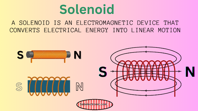
A solenoid is an electromagnetic device that converts electrical energy into mechanical work/linear motion. It consists of a coil of wire, usually wound around a metallic core. 

It create a magnetic field when an electric current passes through it. This magnetic field moves a plunger or armature within the coil, creating linear motion.

Solenoid

Solenoid Valve Working

A solenoid valve is a specific type of valve body used to control the flow of fluids (liquids or gasses). It uses an electromagnetic solenoid to operate a valve mechanism, allowing or blocking the flow of the fluid. It is an electromechanical device used to control medical devices in laboratories.
Solenoid

Types of SOV Valves

1. Direct Acting SOV

Operation: The SOV directly opens or closes the valve.
Application: It is suitable for low flow rates and low pressures.

2. Pilot-Operated (Indirect Acting) SOV

Operation: 
Uses the fluid pressure differential to open or close the valve. The SOV controls a pilot orifice that activates the main valve.
Application
Suitable for high flow rates and high pressures.

3. Two-Way SOV Valve

Operation
Has one inlet and one outlet, controlling the flow in one direction.
Application:
In general-purpose applications where flow needs to be controlled in a single direction.

4. Three-Way SOV

Operation: 
Has three ports; one inlet, one outlet, and one exhaust. It can switch between two different paths.
Application
Used for diverting or mixing fluid flow, commonly found in pneumatic and hydraulic systems.

5. Four-Way SOV Valve

Operation: Has four or more ports, allowing control of multiple flow paths.
Application: 
Typically used in double-acting cylinders or actuators where two pressure sources and two exhaust ports are required.

Applications of Solenoid Valves 

1. Industrial Automation

Control of pneumatic and hydraulic systems in machinery and valves emergency shutdown system.
Used in manufacturing processes to control the flow of various fluids in pneumatic and Hydraulic system.

2. Automotive Systems

Used in Fuel injection systems to provide the supply of fuel.
Automatic transmission systems.

3. HVAC Systems

Control of refrigerant flow in heating and cooling systems.
Used in air conditioning units to regulate temperature and humidity.

4. Medical Equipment

Control of gases in anesthesia machines.
Used in ventilators and other respiratory devices.

5. Agricultural Equipment

Irrigation systems for controlling water flow.
Used in fertilizer dispensing systems.

6. Water Treatment

Control of water flow in filtration systems managed by PLC system.
Used in municipal water supply systems.

7. Home Appliances

Washing machines and dishwashers for controlling water intake and drainage.
Coffee machines and other beverage dispensers.
Solenoid valves are versatile components used in a wide range of applications. Because the ability to provide reliable and precise control of fluid flow.

How to Check a Solenoid

Checking a solenoid involves several steps to ensure it is functioning correctly. Here's a step-by-step guide:

1. Visual Inspection

Check for Physical Damage:
Inspect the solenoid for any visible signs of damage, such as cracks, corrosion, or burnt marks.
Connections and Wiring:
Ensure all electrical connections are secure and that wires are not frayed or damaged.

2. Electrical Test with a Multimeter

Turn Off Power:
Before testing, ensure the power supply to the solenoid is turned off to avoid electrical shock.

Set Multimeter to Ohms (Ω): Set your multimeter to the resistance (ohms) setting.
Measure Coil Resistance
Place the multimeter probes on the solenoid terminals. A functional solenoid coil will show a specific resistance value (refer to the manufacturer's specifications). A reading of zero or infinite resistance indicates a problem (short circuit or open circuit, respectively).

3. Operational Test

Apply Power: With the SOV valve properly connected, apply the correct voltage to the solenoid.

Listen for Activation
A working solenoid typically makes a clicking sound when activated.

Check Movement:
If accessible, observe the movement of the solenoid's plunger or armature to ensure it is moving as expected.

4. Check for Continuity
Set Multimeter to Continuity Mode: If available, set the multimeter to continuity mode.
Test Terminals:
Place the multimeter probes on the solenoid terminals. A beep indicates continuity, suggesting that the coil is not broken.

Precautions

1. Safety First
 Always turn off the power supply before inspecting or testing the solenoid to avoid electric shock or injury.
Wear appropriate personal protective equipment (PPE) such as insulated gloves and safety goggles
2. Correct Voltage
Ensure that you apply the correct voltage as specified by the solenoid's manufacturer. Using the wrong voltage can damage the solenoid.
3. Avoid Overheating
Do not keep the SOV continuously energized for long periods when there is not required to energize. Overheating can damage the coil.
4. Proper Tools
Use a reliable multimeter that can accurately measure resistance and continuity.
Ensure tools are in good condition and rated for the voltage levels you are working with.
5. Check Specifications
Refer to the solenoid's datasheet or manufacturer’s specifications for the correct resistance values and operational parameters.
6. Avoid Moisture
Keep the solenoid and electrical connections dry to prevent short circuits and corrosion.
7. Proper Installation
Ensure the SOV is correctly installed according to the manufacturer's guidelines to prevent mechanical or electrical issues.
8. Handling
Handle the solenoid carefully to avoid dropping or applying excessive force, which can damage internal components.
Follow these steps and precautions to ensure that your solenoid is operating safely and reliably.

Popular posts from this blog

Electronic components list with Images and Symbols

Electronic components function and details Electronic components are used in electronics circuits. These components might be PCB mounted or integrated type, widely used in electronics devices. Digital computers, control devices in industries and household items containing large number of integrated components. It is essential to know how to identify circuit board parts, whether you are an electronic technician or engineer. We made the electronics devices with integrated chips and circuit components. In circuits, electronic components are used. What are active and passive components? Types of electronic components? There are two major types of electronic components . In electronic circuits, there are active and passive components. 1- Active components 2- Passive components Active components These types of components operate with external power supplies.  Passive components Passive components do not require an external power supply. These components energize with circuit signals. Elec

Arduino UNO Pinout with schematic Diagram and Functions

Arduino UNO Pinout and Board components detail The Arduino Uno is a microcontroller board based on the ATmega328P. It has a total of 28 pins, including digital I/O pins, analog input pins, and power pins. Below is a detailed description of the pin functions It offers extensive resources and a wealth of project ideas, making it a go-to choice for educational purposes, prototyping, and a myriad of DIY electronics projects. The  Arduino UNO Pins  and function are described here in details.  Arduino Uno  is a standard board of the company, even though other boards, e.g. micro, Nano, mega, Leonardo, 101, Due and Yen.  Arduino also manufactured IoT (Internet of Things), Bluetooth, GSM/3G, Wi-Fi, and motion sensor boards. Arduino uno Specifications Microcontroller : ATmega328P Operating Voltage : 5V Input Voltage (recommended) : 7-12V Digital I/O Pins : 14 (of which 6 can be used as PWM outputs) Analog Input Pins : 6 DC Current per I/O Pin : 20 mA Flash Memory : 32 KB (ATmega328P) of which 0

Arduino sensors and modules list for Projects.

Arduino Sensors for Electronics Projects What is Sensor? A Sensor is a device used as the primary element that measures physical value and converts it into an electrical signal. Also, we can say that the sensor is a transducer. It measures temperature, distance, light, sound, etc. Sensors and actuators are widely used in Arduino projects. These sensors come with a kit or can be purchased separately. Some of them are compatible with Arduino Uno boards and also Raspberry Pi and other electronic modules. There are a lot of types of Arduino sensor kits available in the market. How many types of Arduino Sensors? There are a lot of sensors used in electronics projects , e.g. robotics cars, moving objects, flying drones, IoT(internet of things), sound and light operation, etc. Here is a list of 45 in 1 electronic sensor that comes with an Arduino sensors kit , and the details of their applications. Analog temperature Sensors KY 013 Temperature Sensor KY-013 is an analog temperature sensor

Arduino Kits for beginners in 2024

Arduino Kits for beginners electronics projects Arduino kits are very simple to learn and widely used in electronic projects . You can make your own projects in a few minutes. Making a circuit on a PCB is a hard job, and it requires excellent skills in soldering. Also, it consumes a lot of time. Assembling components is another problem. But electronic portable kits solve the issue. You can gain knowledge from Arduino starter kits on Amazon. It includes project books and different varieties of sensor modules. We directly connect on the breadboard and reconnect in a few steps. Arduino Uno Starter Kit (official) The official starter kit is from the original manufacturer. This is a complete package, including the Arduino Uno kit Manual. This manual has practical images and schematic diagrams to understand well.   The manual covers not only project-making areas; but also information about Arduino IDE software installation on Windows/macOS X and Linux. Every Project/lesson comprises exam

Led Matrix display interface with Arduino uno

LED matrix display pins with Arduino Interface    An 8x8 LED matrix is a grid of 64 LEDs arranged in 8 rows and 8 columns. It is commonly used in  various display and lighting applications, such as digital clocks, scrolling text displays, and graphical displays. Each LED can be controlled individually to create patterns, animations, or characters. I will introduce 788bs as a common anode red color 8x8 LED matrix display m odule. We use it in many electronics displaying items, e.g. electronic clocks. also for moving message displays, displaying games, etc. We use a dot matrix display with an Arduino UNO board directly, sometimes in projects. But for some projects, we use a max7219 chip or 74hc595 for dot matrix driver as required in our projects. led Matrix 8x8 Pin Configuration Each LED matrix can have a slightly different pin configuration, but a common arrangement is as follows: [LED Matrix] Pin 1 - Row 1 Pin 2 - Row 2 Pin 3 - Row 3 Pin 4 - Row 4 Pin 5 - Row 5 Pin 6 - Row 6 Pin

Resistor Calculator with Graphical Chart

Resistor Calculator for measuring resistance Resistor calculator is a very useful tool for anyone working on electronic experiments or projects. It is easy to use and has a simple design. To get resistance for Led voltage drop or your circuit resistance, you can use an online calculator or look up a formula. We can use it for voltage drops or led current limiting. Online resistor calculator It is a simple and easy-to-use online resistor calculator instead of using formulas. It comes with different bands e.g.3 band, 4, 5, and 6 bands. The program calculates resistor values. # Get in touch with more interesting topics ……… 1- How to use a led Matrix with Arduino . 2- Arduino books for projects . 3- Best Arduino kits for beginners . Standard Table For Calculating 4 Band Resistors Online Resistor Calculator (4 Band) Graphical Resistor Calculator Graphical Resistor Calculator is a Free Software to easil

555 Timer IC, Pinout and Function details

555 Timer IC Pinout and applications: We widely used 555 timer IC in electronic projects . This chip has multi-function time-based output signals. We can use 555 IC chips with the Arduino or make separate projects. It is available with different brand names, i.e., LM555, NE555, and SE555. But it is originally manufactured by Texas Instruments. The chip is manufactured in different packages, e.g. SOIC, PDIP, VSSOP. For more details, the 555 timer IC datasheet is available at the Texas official site. We use it for time-based operated siren circuits, control motor speed, and operating led flasher circuits. It can produce a lot of functions, e.g., oscillation, Astable. Bistable, Monostable, flip-flop logic, and pulse width modulation. How 555 Timer work ? You can get a lot of solutions from the chip if you want to understand how it works. There are a lot of timer projects and applications, e.g., timer-controlled circuits, sound, LED flashers, and more. 555 Timer IC Pinout The circuit di

Arduino uno Project for led blinking from start

What is Arduino Uno? The Arduino Uno is an electronic board that has  the ATMEGA 328P microcontroller. It has analog and digital input/output pins. We use it in simple projects, e.g. led lights, and also complicated robotics projects.  Let's  get started with   Arduino Uno  to run our first program. As we use it with different machines e, g. Windows, Apple, Ubuntu, mobile, etc.  as usual Arduino programming is difficult for newbies, but if you get in touch with this Arduino tutorial, it could be helpful. Getting Started with Arduino Here, I will discuss especially the Windows operating system and also a little another operating system. First, I will discuss how to interface with the Windows operating system. Requirements for Arduino setup Arduino Uno            Amazon USB Cable A-B male (usually used for printers)   Amazon Laptop/Desktop with Windows 7, 8, 10 The IDE Software Led (can choose any color)    Amazon Resistance (value of 230 Ω) Amazon   Setup Arduino ide Get the lates

Arduino Apps and software for genius

  Arduino apps for Android and Windows We know that Arduino Apps is used for programming, but we could run it on Windows and Android. As it depends on the availability of a programming device for our projects. This application also works for the Arduino Bluetooth Android project. These Applications can help to learn and create electronic projects . I will describe the functions and introduction of the following: application and also support systems required to run. List of Arduino programming applications for Android Android Apps for Electronics Solutions. It is an easy-to-use Arduino Application in Apple Android. Arduino Droid app for Mobiles Droid v   4.9.1 . Droid is a short form of Android; it means a robot. The Droid app works on PC and, an example of Arduino Android is also available. It includes IDE, compiler, and up-loader. the mobile memory should be enough, and it can't be set up on an SD card for the Android protection policy. The second picture shows a menu, it l

Contact Form

Name

Email *

Message *